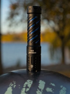
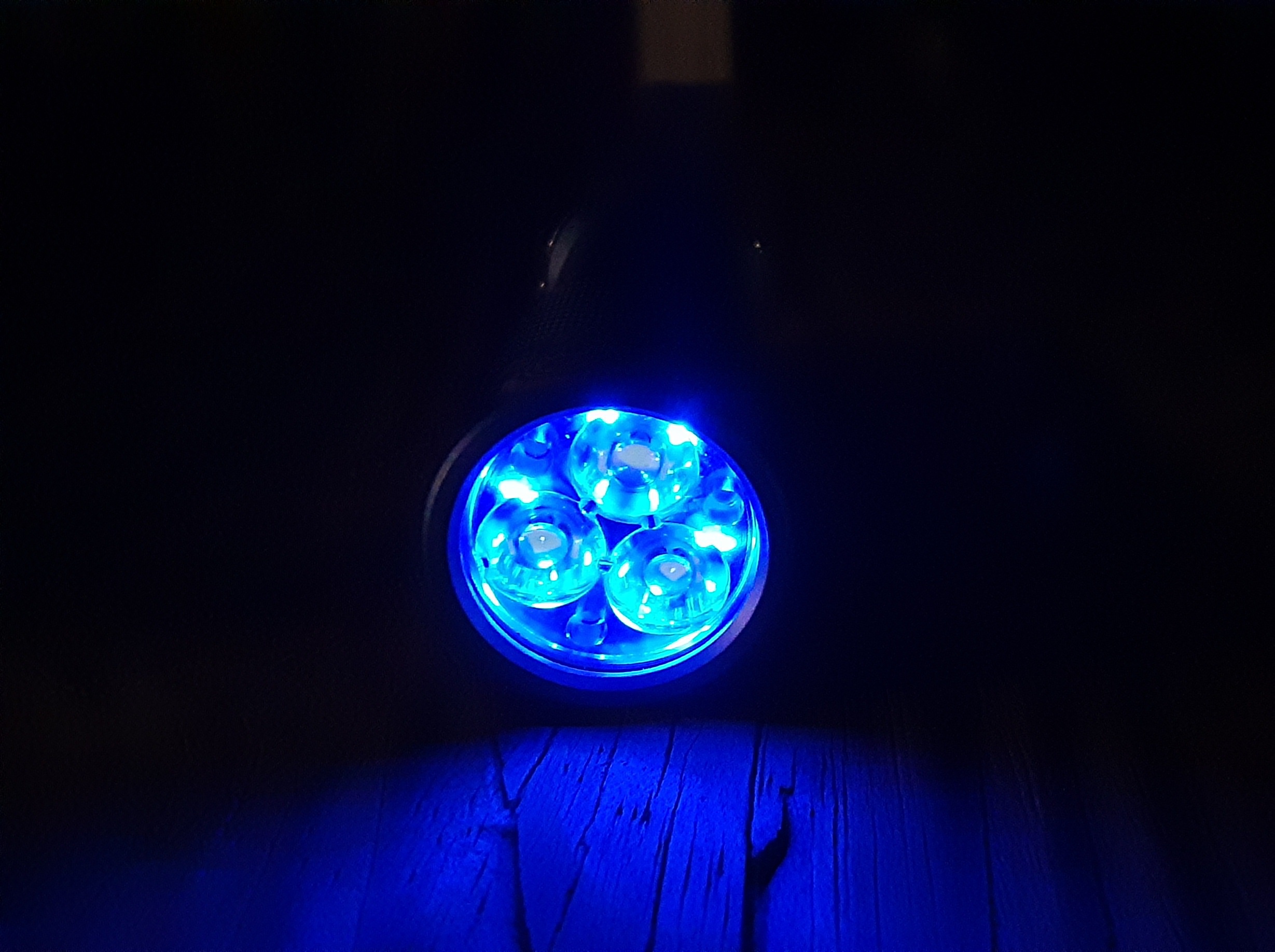
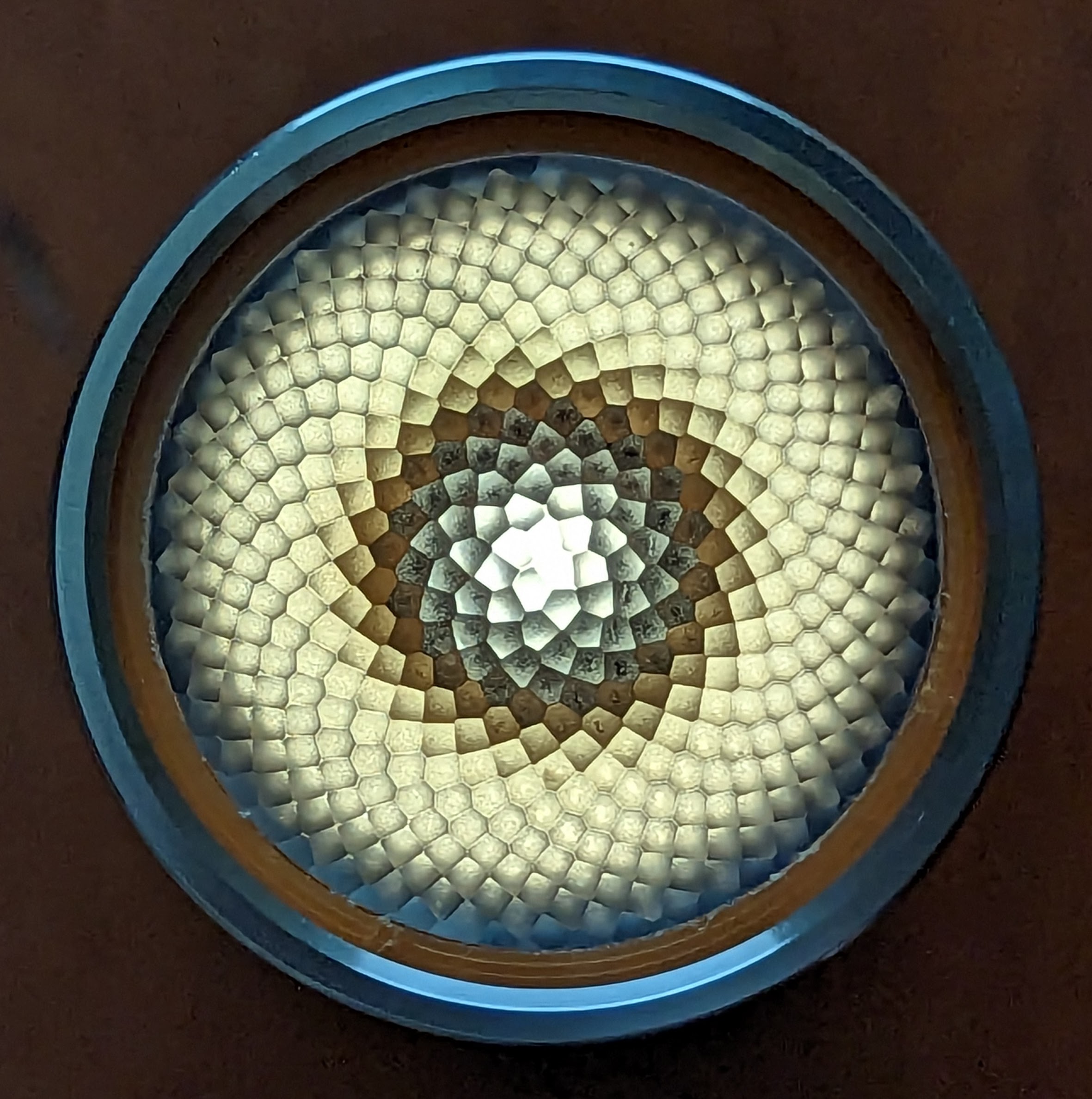
Hey guys, here’s my latest FW3A t1616 mod. This time with orange, pink, and warm white aux
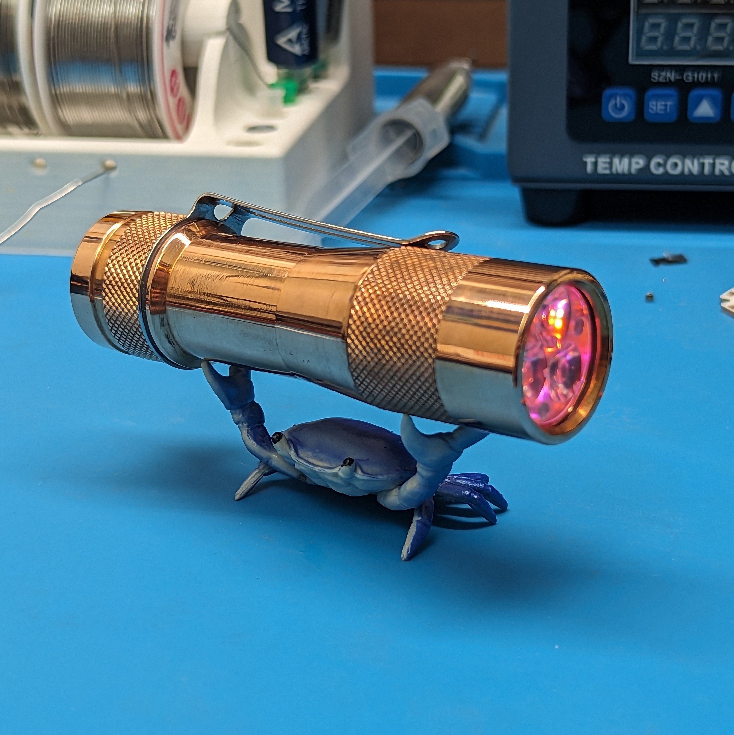
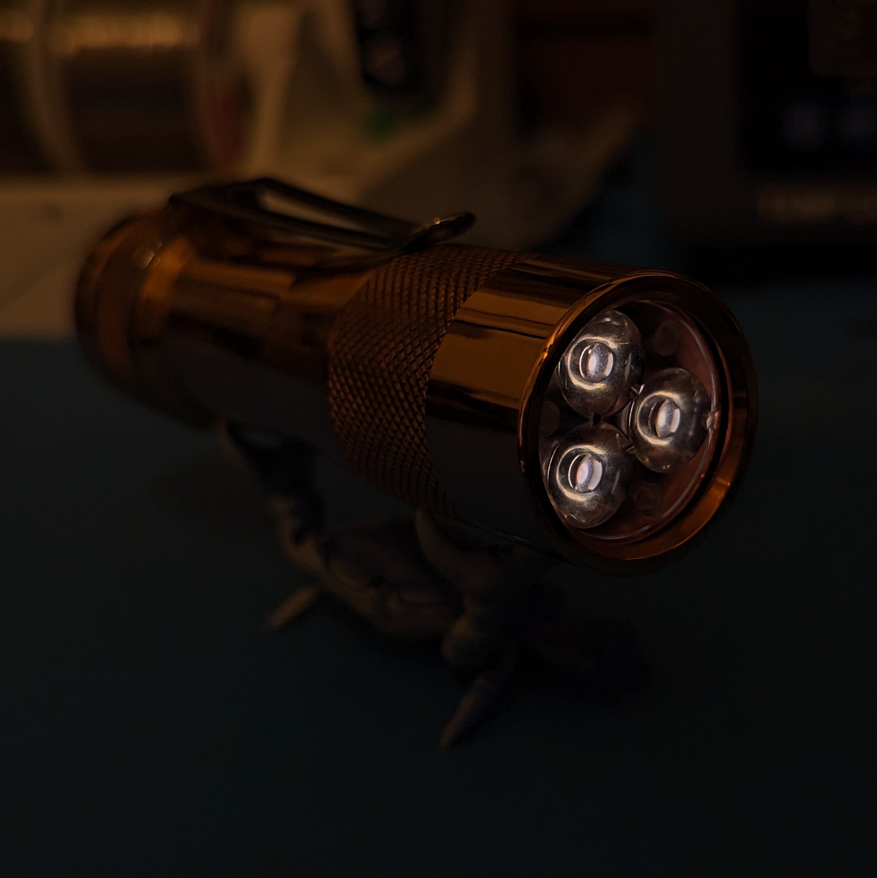 Just look at that moonlight 👀
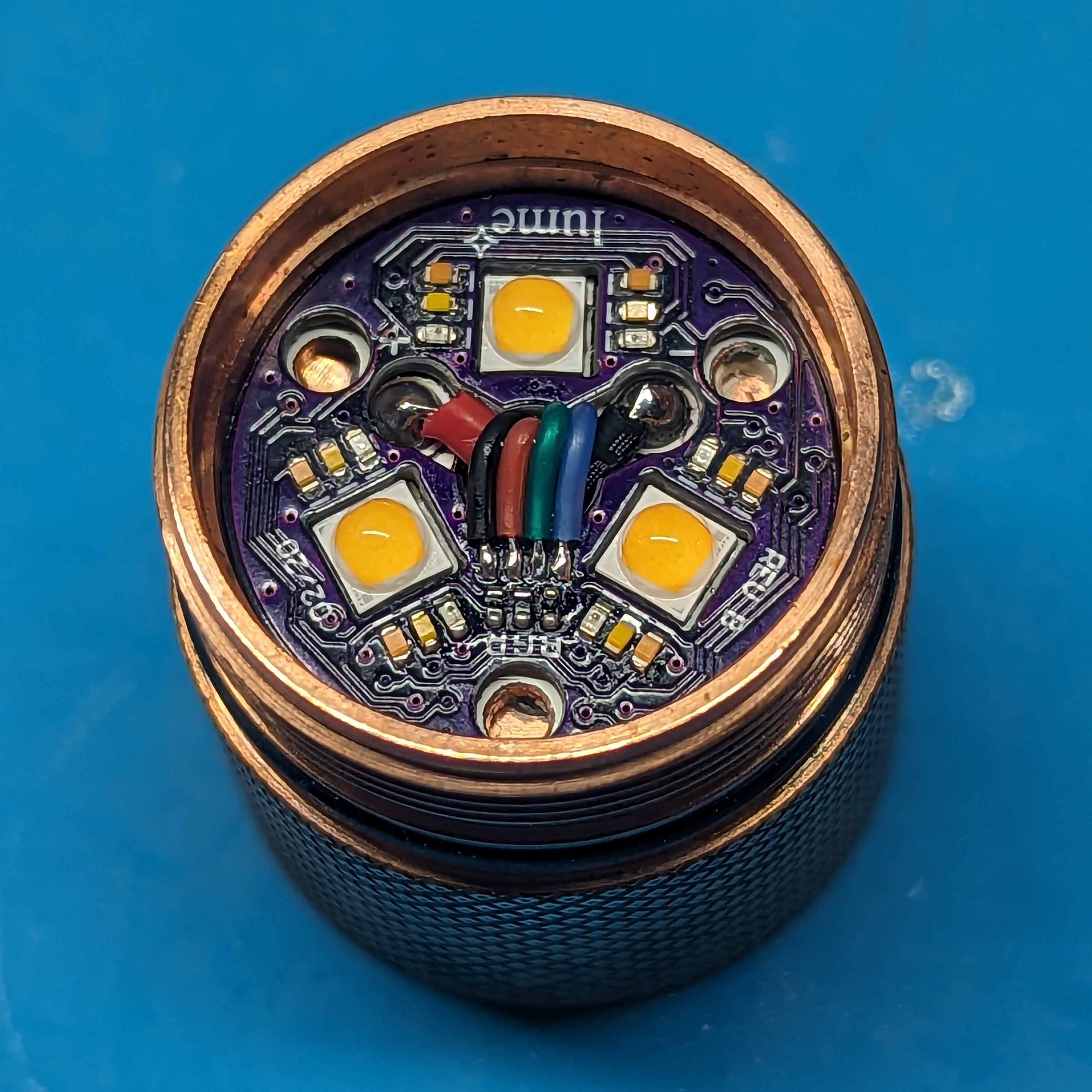
Clean as always, beautiful work.
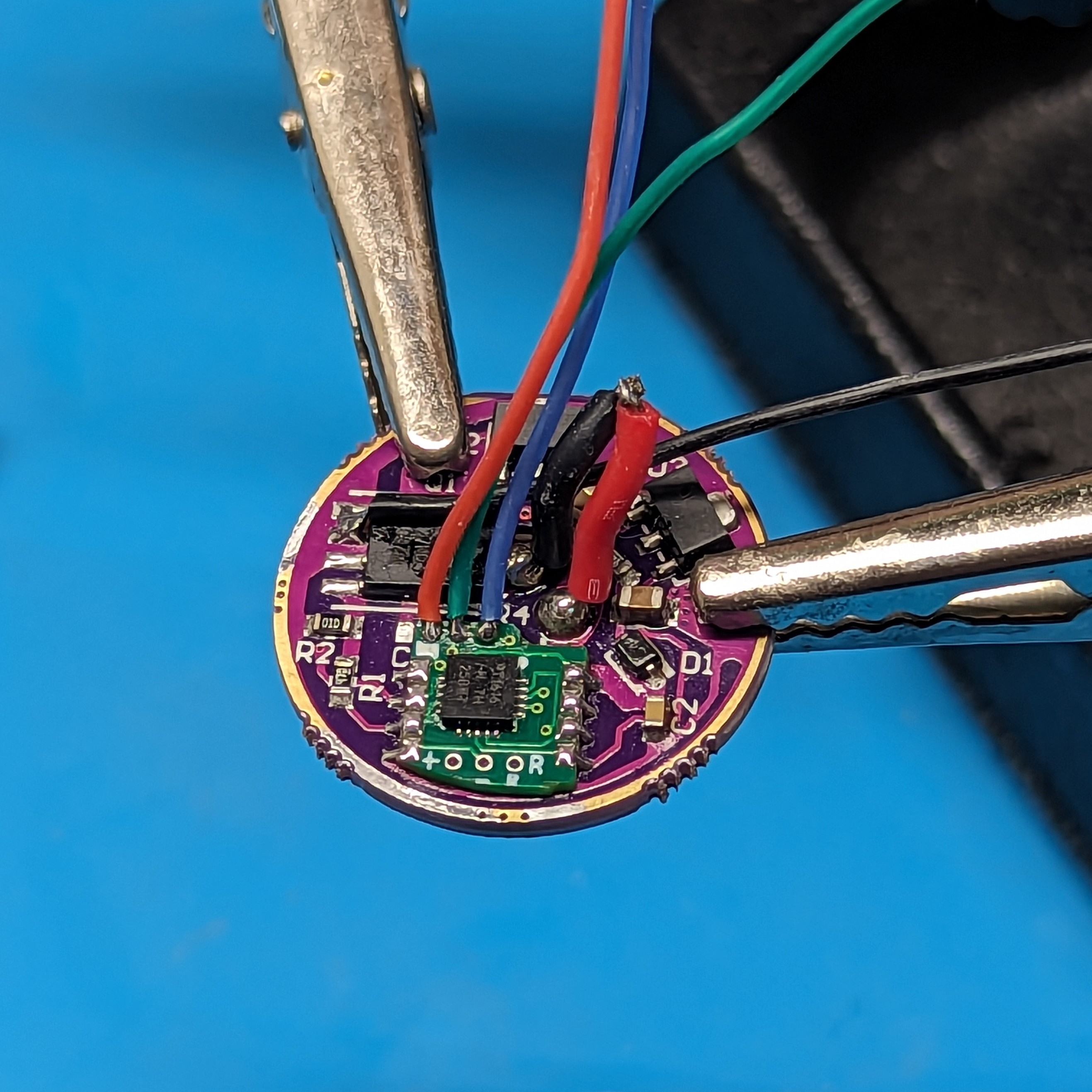
MCU swap.
Ahh I see you have collected the Infinity Stones. How very impressive Mr. Adair.
Perfectly balanced, as all things should be
A thing of beauty!
When did you switched to 0402 LEDs?
Do you find them easier to manage?
A few months back. The 0603 emitters liked to stick together
You guys are knocking it out of the park with these MCU swaps. You’d think Lumintop would catch on, but instead they are killing the FW platform. So unfortunate.
Love that aux combo!
Nice job man!
Thanks bro!
Wait, what exactly has happened here? Did you replace the whole driver in the FWAA? Was it an existing 1616 board where you swapped the leds, or what? I had somehow thought the FWAA was not an Anduril light.
This is the FW3A. I swapped the MCU on the driver from a t85 to t1616 with an adapter board that also has pads for RGB aux
Aha nice, and presumably the adapter has flashing pads too. Very nice work, though I don’t understand why start with the FW3A to begin with. Sorry about the mixup with the FWAA.
Yes it does, but you can only get to them when the driver is out.
Because I love the FW3A 😂
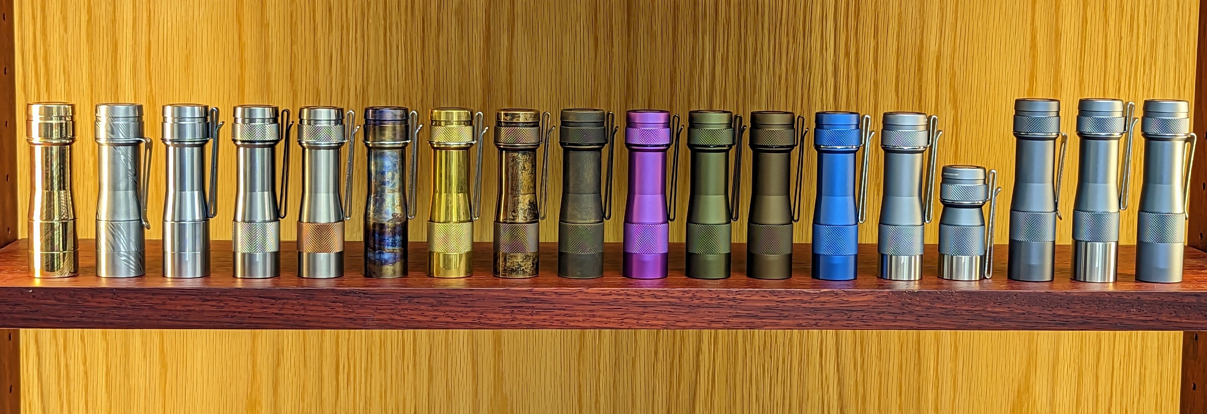
Very nicely done. I just ordered a bunch of Oshpark boards to try my hand at this. I just need to get some t1616’s and some more tiny, tiny LEDs.
Ahh yes the hidden recipe: warm white + some kind of pink or purple + a third colour. Always amazing.
Mine! Lol
Seriously nice work!
Trying to figure LW out still
Perfect soldering as expected. I can’t help it but my OCD has made me notice that you have the red and blue wires swapped on the aux board, not that it matters in this light.
Also is that moonlight level? The lowest few levels acted weird before you disabled dynamic underclocking. I have been doing some experiments myself, with dynamic unclocking enabled and disabled. I ended up making a new smoother ramp while keeping it enabled.
Btw, what happened to your anduril2 fork? It is no longer visible on GitHub, did you make it private?
Thanks! And they’re not swapped. That’s the correct order.
I disabled underclocking and set the default level to 3. 1 and 2 are very dim or don’t work at all depending on the Vf of the emitters.
Yep, it’s currently private
That’s the correct order
Stupid me, you are right. I can’t tell “R” from “B” from the label on the actual board. I think I swapped all of mine on purpose because I wanted the sequence of colour change to go from outside to inside. Again, not that it matters, because none of mine are RGB lol.
Thanks for continuing to post your excellent content on Lemmy!
Absolutely. This is my new home

